![Simpled Logo Size-1.jpg]](https://learn.simpled.uk/hs-fs/hubfs/Simpled%20Logo%20Size-1.jpg?height=50&name=Simpled%20Logo%20Size-1.jpg)
Product Overview:

What's Included:
1x Exterior panel(Rubber pad include)
1x Interior panel
2x Keys 
1x Deadbolt Assembly & Strike Plate
1x Installation Kits
1x Mounting Plate
1x Drilling Template
1x Phone Tag (Sticker)
2x Proxy Fobs

Specifications:
| Model | KF-SP |
| Materials |
|
| Lock weight | |
| Unlocking methods |
Bluetooth (via the app) eKeys |
| Colour | Black |
| Dummy password | |
| Doors applicable | |
| Working voltage | Nominal voltage of 6.5V power supply with external power interface |
| Door thickness |
|
| Data capacity |
Fingerprint: 100 Password: 250 Card: 1000 |
| Working temperature | -10℃-55℃ |
| Working humidity | 0-95% |
Note: Default admin password in initialization state: 123456 or 000 or 000000.
Operation Instruction:
Restore factory setting 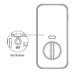
Press and hold the reset button on the lock
And enter“000000#"the lock will restore to
factory settings, clearing all passwords and
mobile administrators
Installation Steps: 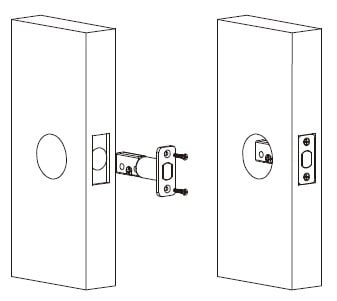
1. Install the Bolt and Strike Plate
-
Insert the bolt into the door.
-
✅ Important: Make sure the bolt is in the retracted (unlocked) position.
-
Install the strike plate on the door frame. Ensure the bolt will align and center properly within the strike when extended.

2. Install the Exterior (Outside) Assembly
-
Feed the cable from the exterior assembly through the door hole.
-
✅ Note: The cable should go below the bolt as you insert the assembly into place.

3. Attach the Mounting Plate (Interior Side)
-
Hold the exterior assembly flush to the door.
-
Route the cable through the hole in the mounting plate.
-
Secure the mounting plate with the provided screws.
4. Connect the Cable 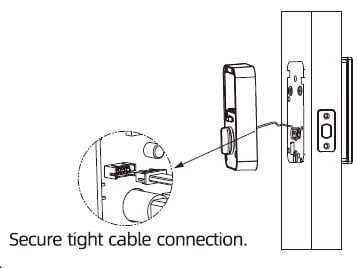
-
Connect the cable to the interior assembly’s PCB (circuit board).
-
🔌 Tip: Firmly press the connector in using your thumbs until it is fully seated.

5. Attach the Interior Assembly
-
Place the interior assembly onto the mounting plate.
-
Use the included screws to secure it tightly.
6. Test the Lock Mechanism and Door Alignment
✅ IMPORTANT: Before inserting batteries: 
-
Test the lock manually using the thumb turn and the physical key.
-
The bolt should move smoothly without resistance.
-
If the bolt sticks or feels obstructed, double-check your installation steps for alignment.

7. Insert Batteries
-
Install 4 AA alkaline batteries into the battery compartment.
-
Replace the battery cover once done.
-
Your smart lock is now powered.

8. Setup the Built-In Door Sensor (Auto-Lock Feature)
-
The lock includes a built-in door sensor for auto-lock functionality.
-
Slide out the sensor module from the back of the interior assembly.
-
You may need to temporarily remove the interior assembly to access it.
-
-
Stick the magnet onto the door frame, positioned close to the sensor.
✅ You're Done!
Your Simpled KF-SP Smart Lock is now installed and ready for use.
Simpled App Installation Guide
Useful Information:
Functionality of Simpled Smart Locks Without Network Access
Rename Your Locks in the TT Lock App